PROJECT 360
BODY MODIFICATIONS
FLUSH-MOUNT WINDSHIELD
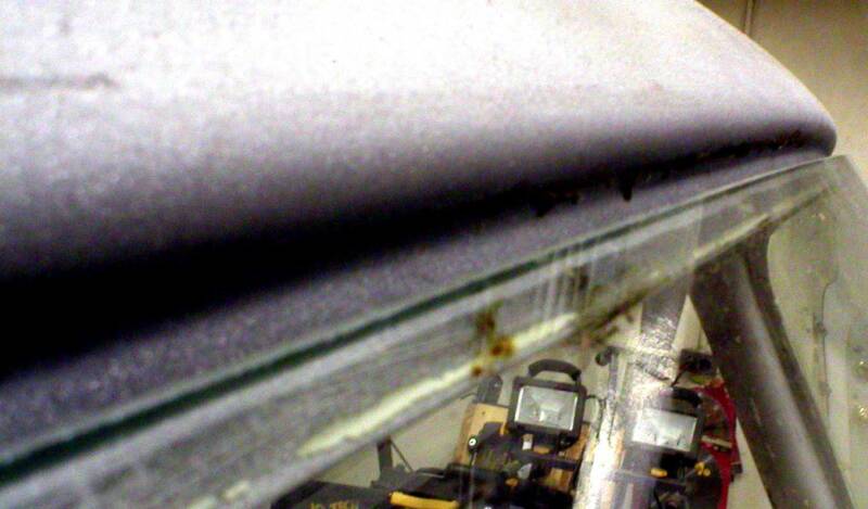
In order to flush mount the windshield, it is necessary to mock up the windshield to see what will be needed to mount it properly. Picture at left shows the upper edge when properly aligned. There is an approximate 1/4" gap along the body line for the flexible "T" molding and has a sufficient body flange for sealer/adhesive.
Click here to add text.
R. A. SNIVELY DESIGNS RICHMOND, INDIANA
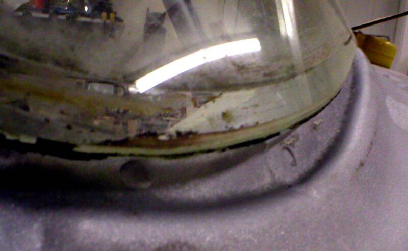
The initial mock up shows the lower edge gap that will need to be addressed. A solid steel rod will be welded along the lower opening edge to provide a filler. Once completed, a flange will then be welded to extend upward to provide a surface for the glass sealer/adhesive.
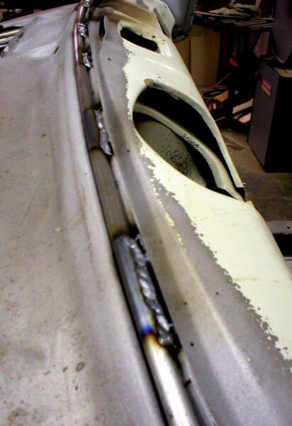
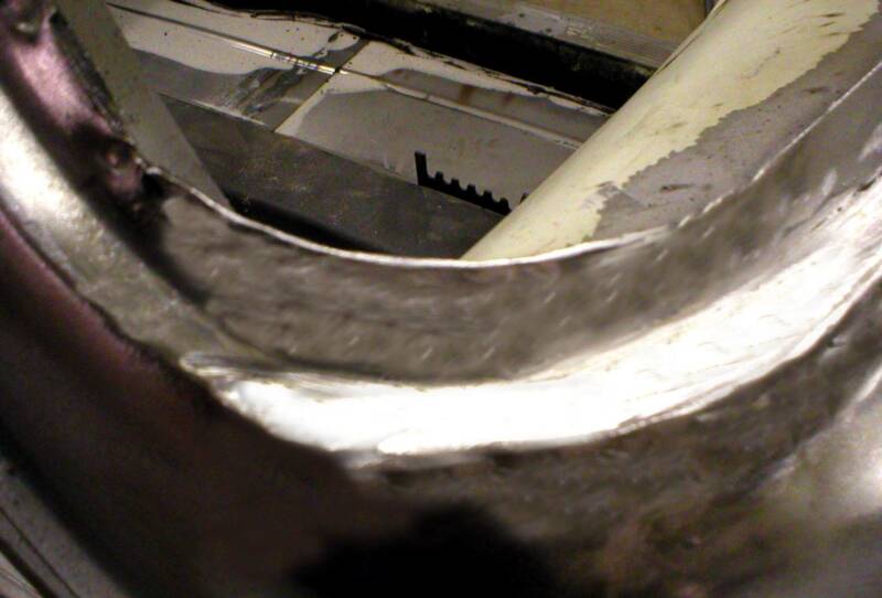
The pictures above depict the sequence of welding a 5/16" solid steel rod into the lower windshield opening. It was first centered then tack welded to the opening. Each subsequent tack weld was worked from center to outer ends. Also, the first welds were placed inward and not along the outer edge until the rod was fully positioned. The rod was heated and bent to fit the lower corner contours. Once this was completed, then the rod was tacked along the outer edge and each weld was only tacked and constantly moved from place to place to help dissipate the heat. This helps reduce warping substantially. The picture below depicts how these tacks appear during this process.
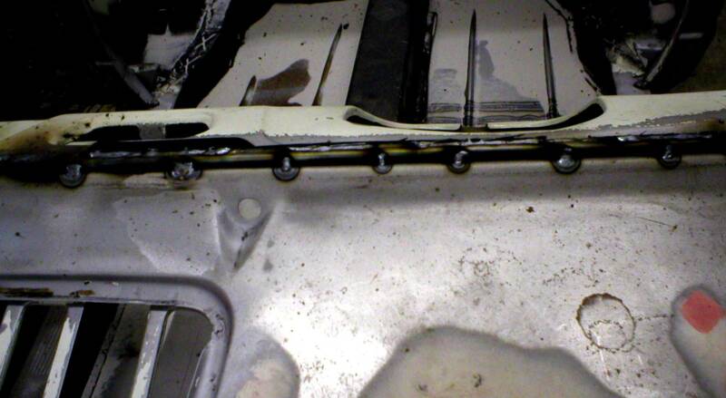
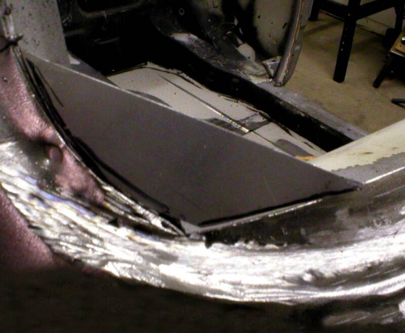
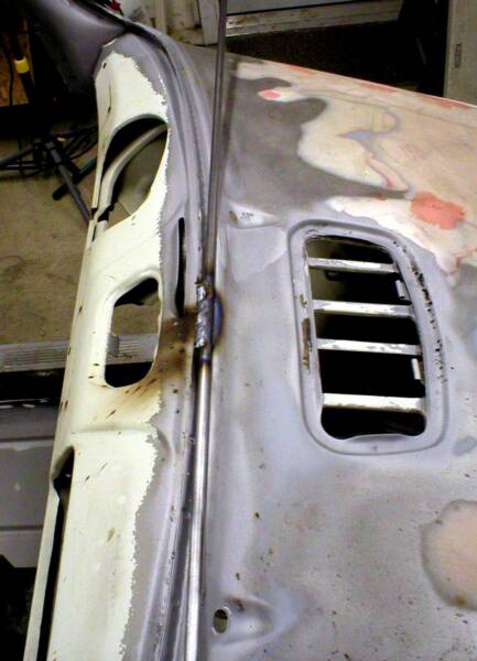
Once the rod was fully welded along the inner and outer edges, then ground smooth, a flange was welded to create a body "pinch weld" that will provide an area in which the windshield will seal. The pictures at the left show the small filler piece that was necessary to create a seamless flow of the newly added flange along the bottom and the factory flange along each "A" pillar.
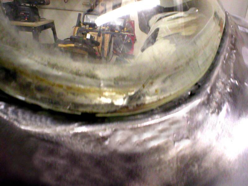
This picture shows how close the tolerances are held along the windshield edge and how smooth all the new metal becomes with careful cleaning and grinding. Body filler will be used to smooth any imperfections.
The new metal along the lower edge now allows the factory glass to sit in the opening and rest on the body flanges.
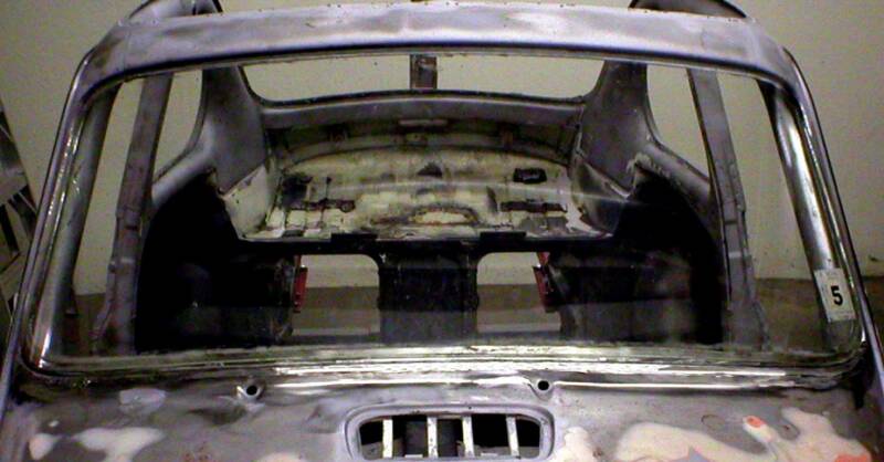
RELOCATING TAIL LIGHTS
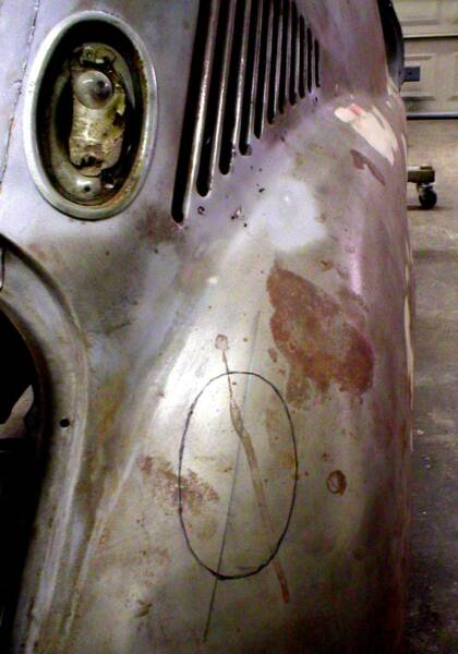
As the picture at the left shows, the taillights that were originally mounted in the valance panel below the rear window (and above the rear deck lid) are being relocated to the rear fenders. It has become apparent that when a convertible type top is folded in the open position, it will obstruct the rear view of the taillights. A reference line was first determined as to not disturb the dynamics of the original mounting angle of the lights. This will help in the overall function and aesthetics of the lights.
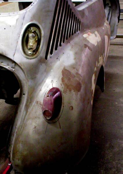
An original lens was taped in position to help visualize the new location of the taillights. It appears as though Subaru should have done it this way back in '69.
There is also extensive
research being done for LED type tail lights. Click here for more information.
to be continued................
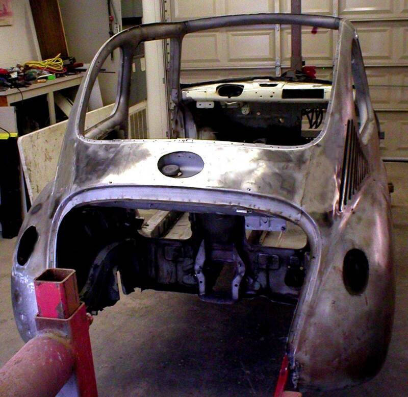
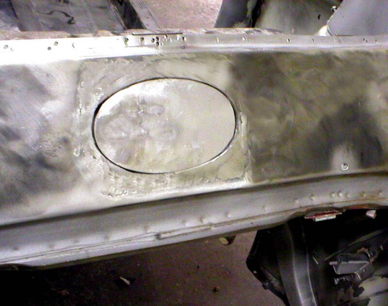
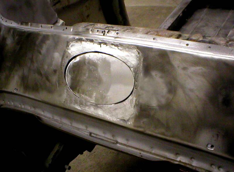
From this angle you can see the original tail light locations have been filled with sheet metal, welded, and ground smooth. The new locations on the rear fenders have been cut out. Also, the fuel filler door has been altered and will become an oval shape that will match the oval shape of the Subaru Star Cluster emblem that will be mounted on it. The door will be hinged from the right side as to not interfere with the filler neck of the fuel tank.
GAS FILLER DOOR ALTERATION
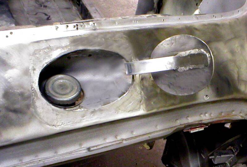
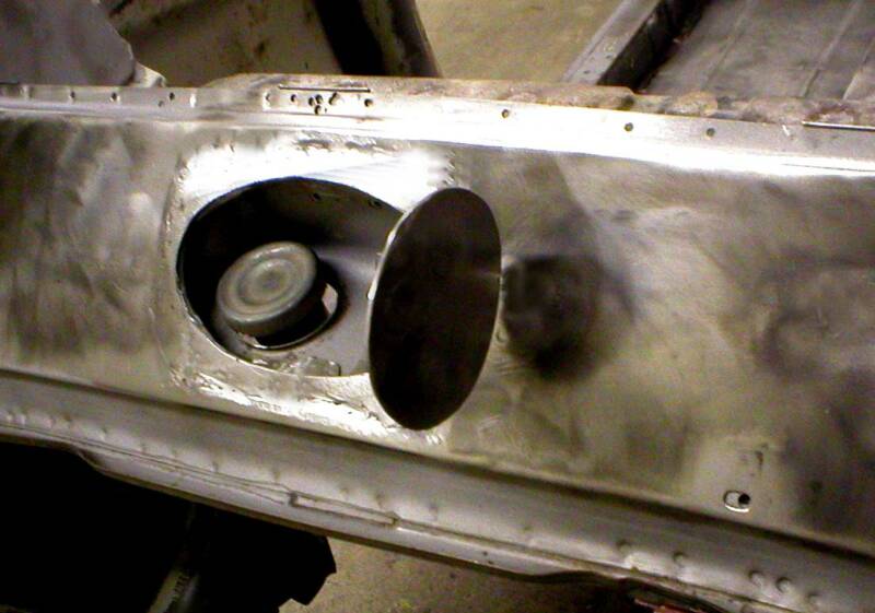
The gas filler door was originally square in shape and hinged at the top. Since PROJECT 360 will have a folding soft top and a new look to the rear, Bob thought it might be a nice touch to reshape the gas filler door so it would match the oval shape of a Subaru Star Cluster emblem that will eventually adorn it. The two pictures above and the two below show what this feature looked like after the custom fabrication and while it was still in the bare metal stage. The gas tank was temporarily installed to check for necessary clearances of the strap hinge and filler neck / cap. A latch will eventually follow.
DOOR CHECK STRAPS
Although somewhat small in size and seemingly insignificant, the door check straps on all 360 sedans are prone to failure. When this occurs, the door will open into the quarter panel and create significant damage. Since Bob is spending much time trying to get the body in good shape, he felt it was necessary to address this problem and improve on the original design. What you see in the following pictures is his solution and a very STRONG check strap!
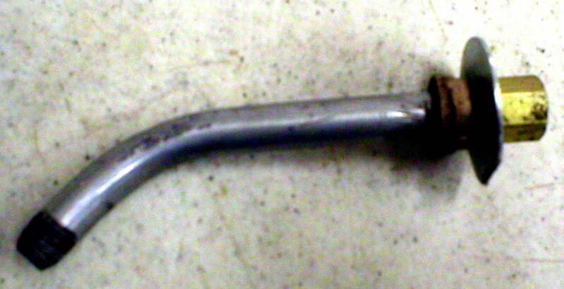
A piece of 1/8" pipe nipple with the proper bend creates a very strong check "strap". It's so simple, yet doubles as both the door check and a small wire conduit for wiring to be routed into the door. In the picture above, the right end is the end that fastens to the door rigidly and will move with the door. The large, thick washer will be on the inside of the door creating a reinforced wall at the attached area.
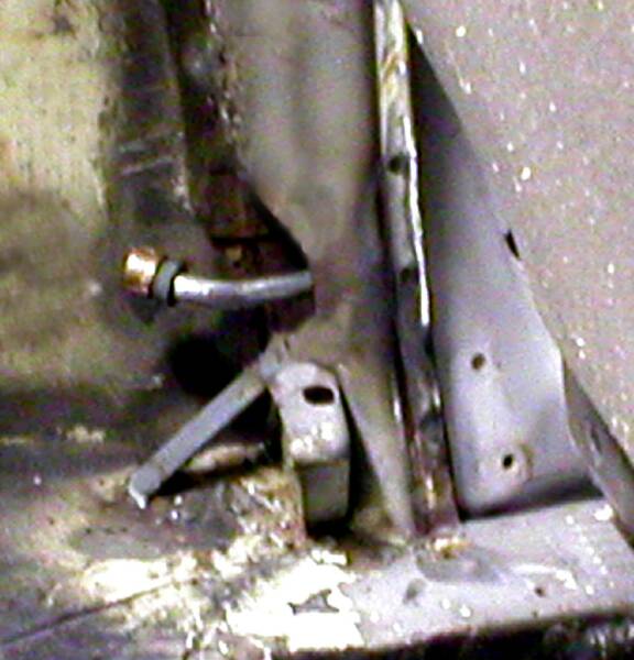
This is what the check strap looks like when the left door is opened to its fullest position. The rubber grommet is placed in a reinforced area of the door jamb just below the bottom door hinge. Although not easily detected in the picture, the factory recessed area of the jamb for the hinge clearance was extended lower to accommodate the new strap. This area also received an 18 gauge metal plate that was plug-welded to the inside of the jamb to help strengthen the factory post. There is also an access hole in the door to allow proper access to the inside of the door to attach the strap.
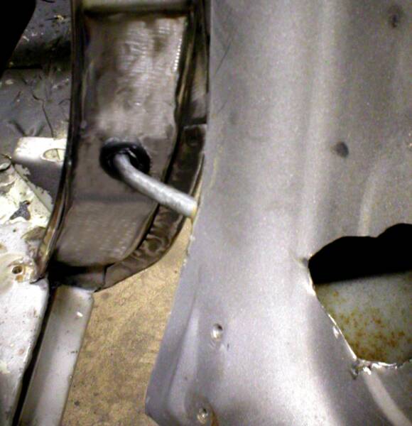
With the left door closed, you can see where the strap is located in the quarter panel. The threaded end of the pipe nipple strap has a brass pipe cap threaded onto it and has a hole drilled into the cap to allow wires to pass through the pipe. Also, there is a stiff conical shaped rubber cushion that provides a softer feel to the door when it reaches its fully opened position. There was some removal of metal from the inside of the door jamb post, but as can be seen in the picture, an additional brace along with additional welding of the factory metal jamb post was necessary to stiffen the entire area.